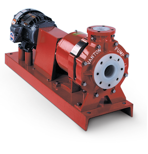
Magnetically Driven, Sealless, Centrifugal Thermoplastic Pumps
meet ANSI B73.1 standards
- Flows to 400 gpm (91 m3/h)
- Heads to 180 ft (55 m)
- Temps to 225°F (107°C)
- Construction: PP, PVDF
Vanton CHEM-GARD® CGM magnetically driven end suction process pumps are sealless, single stage, volute type centrifugals that conform to Hydraulic Institute Standards. All fluid contact parts are molded of solid polypropylene (PP) or polyvinylidene fluoride (PVDF), which are chemically inert and abrasion resistant. As a result CGM pumps eliminate corrosion associated with metal pumps, wicking and contamination associated with fiberglass pumps, and porosity/delamination associated with plastic lined metal pumps.
| Items |
 /Asset/chemgardCGM_eng.png /Asset/chemgardCGM_eng.png 1036 Mag-Drive CHEM-GARD® CGM 1-1/2 x 1 x 6 Inch (in) Size Horizontal Centrifugal Pump |
/Asset/chemgardCGM_eng.png 1037 Mag-Drive CHEM-GARD® CGM 3 x 2 x 6 Inch (in) Size Horizontal Centrifugal Pump |
/Asset/chemgardCGM_eng.png 1038 Mag-Drive CHEM-GARD® CGM 3 x 2 x 8 Inch (in) Size Horizontal Centrifugal Pump |
/Asset/chemgardCGM_eng.png 1039 Mag-Drive CHEM-GARD® CGM 4 x 3 x 8 Inch (in) Size Horizontal Centrifugal Pump |
/Asset/chemgardCGM_eng.png 1040 Mag-Drive CHEM-GARD® CGM 4 x 3 x 9 Inch (in) Size Horizontal Centrifugal Pump |
|||||
| Description |
Magnetically Driven, Sealless, Centrifugal Thermoplastic Pumps
|
|||||||||
| Flow Rate | Up to 400 gpmUp to 91 m³/h | |||||||||
| Head Size | Up to 180 ftUp to 55 m | |||||||||
| Temperature Range | Up to 225 ºFUp to 107 ºC | |||||||||
| Construction Material | Polypropylene (PP) Polyvinylidene Fluoride (PVDF) | |||||||||
| ANSI Designation | AA | A-10 | A-60 | A-70 | A-70 | |||||
| Suction Size | 1-1/2 in | 3 in | 3 in | 4 in | 4 in | |||||
| Discharge Size | 1 in | 2 in | 2 in | 3 in | 3 in | |||||
| Impeller Diameter | 6 in | 6 in | 8 in | 8 in | 9 in | |||||
| Dimension CP | 17-1/2 in | 23-1/2 in | 23-1/2 in | 23-1/2 in | 23-1/2 in | |||||
| Dimension D | 5-1/4 in | 8-1/4 in | 8-1/4 in | 8-1/4 in | 8-1/4 in | |||||
| Dimension X | 6-1/2 in | 8-1/4 in | 9-1/2 in | 11 in | 11 in | |||||
| Dimension Y | 4 in | |||||||||
| Dimension HA | 12 in | 15 in | 15 in | 18 in | 18 in | |||||
| Dimension HT | 3-1/2 in | |||||||||
| Dimension HB | 39 in | 52 in | 52 in | 58 in | 58 in | |||||
| Note for Dimension HA and HB | Baseplate dimensions will vary slightly with motor frame size. | |||||||||
| Features |
Every Vanton pump is fully tested to verify performance with all data permanently recorded. |
|||||||||
| Additional Information |
High performance, permanent, rare-earth magnets transmit power, with the inner magnet rotor assembly isolated from the pumped fluid by a thick-walled PP or PVDF encapsulation. A non-metallic containment can assembly reduces losses in magnetic force and pump efficiency by eliminating troublesome eddy currents. With no seals to fail, and no metal contacting the fluid, these pumps are ideal for leak proof transfer of corrosive, toxic, hazardous and volatile liquids, and for handling of high purity water, reagent grade chemicals and other fluids that must remain contamination free. CGM pumps can withstand the same nozzle loadings as metal pumps because the rugged thermoplastic wet end is supported by a protective structural metal armor. Available with ANSI centerline suction and discharge, CGM pumps fit where conventionally sealed ANSI pumps were installed, without disturbing existing piping. The wet end is comprised of solid, thick-sectioned, stand-alone components (unlike plastic linings), that are easily replaced, maximizing uptime while minimizing cost. The heavy-duty pump casing, stationary bearing housing and impeller are furnished in solid molded polypropylene and polyvinylidene fluoride. The inner magnet rotor assembly is encapsulated in PVDF or polypropylene, and the stainless steel large diameter shaft is isolated from the fluid by a thermoplastic sleeve assembly. (Pump opened to show solid, stand-alone thermoplastic casing, impeller and bearing housing.) |
|||||||||
| Note |
All dimensions are approximate and not to be used for construction purposes. Pump dimensions conform to ANSI B73.1. Design specifics subject to modification as dictated by ongoing product improvement programs. |
|||||||||
|
|
||||||||||
